![]() Motorrad
Elektrik Omega 450 Alternator Kit
Motorrad
Elektrik Omega 450 Alternator Kit
Please read this entire guide BEFORE
beginning work. While installation is very straightforward, proper
electrical and mechanical practices must be followed for safety
and best results. If you are unfamiliar or uncomfortable with
doing this work, please seek a qualified service provider for
installation.
Contact Motorrad Elektrik at (256)442-8886,
or email motoelekt@mindspring.com
for tech support or any questions regarding installation.
Warranty and Disclaimer
The components of this kit are warranteed against defects in materials or workmanship by their manufacturer(s), for a period of one year from installation. Parts damaged by abuse, neglect, or improper installation or use will not be warranteed.The seller hereby expressly disclaims all warranties either expressed or implied including any implied warranty of merchantability of fitness for a particular purpose, and seller neither assumes nor authorizes any other person toassume for it any liability in connection with the sale of said products, or for any damages or consequences arising from their use.
Important Information
The Omega alternator is rated for 450 watts of output, but even with that kind of superior charging power it IS POSSIBLE to overload the system if too many electrical accessories are turned on at the same time, and continuous stop ? and ? go traffic must be endured. Also bear in mind that under those same conditions the engine may SERIOUSLY overheat!
To prevent system overload and possible damage, you must total the amount of wattage each consumer requires. This information is usually on the packaging or ads for the product, or can be obtained from the manufacturer of the item. Typical examples would be driving or fog lights, usually consuming 55 watts each, or a heated vest that draws 75 watts.
As a loose rule of thumb, the basic requirements of ignition and standard headlight / tail lights are usually about 100 watts. Adding this to the total amount of extra consumers wattage will give the amount of output required from the alternator.
DO NOT EXCEED 450 WATTS OF TOTAL SYSTEM DEMAND! Damage will likely result, and the warranty may be void.
Be more cautious in high ambient temperatures about continuous operation near maximum output: under these conditions, the alternator may get very hot, and output may degrade slightly from excessive heating. This may be especially true for bikes with full ? frontal coverage fairings, oil coolers, or other accessories that may block airflow to the engine. It is strongly suggested that 1970 ? 73 /5 models should use a 1974 ? 78 /6 type front engine cover when fitted with this alternator, for greatly improved component cooling.
Installation
 Disconnect
ground cable
Disconnect
ground cable
 Regulator location, early
 Regulator
location, later
Regulator
location, later
1. Disconnect the battery ground cable. Failure to do this may cause damage to components, and warranty will be voided. Do this every time the front cover is removed, without exception.
2. Remove the fuel tank, observing all safety precautions for
handling inflammable liquids.
RICK... NEED THESE THREE IMAGES! NOT INCLUDED WITH OTHER HI RES IMAGES, I CLIPPED THEM FROM PDF FILE!
 Remove
old voltage regulator
Remove
old voltage regulator
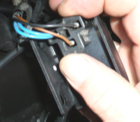 regular
blue, black, brown connector
regular
blue, black, brown connector
 Install
new voltage regulator
Install
new voltage regulator
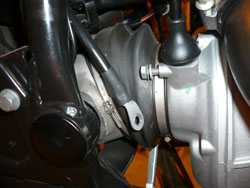
3. Remove the voltage regulator on
the right side of the frame by unplugging the single connector
and removing the 2 mounting fasteners. On 1970-80 models, the
regulator is a metal box about 2" x 3", closer to the
front edges of the fuel tank on the right side of the frame. On
later models, the regulator is usually a slightly smaller red
and black plastic box located about half way down the right side
of the frame. All versions use the one connector plug with 3 wires,
blue, black and brown. Install the new regulator.
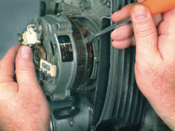
 Front engine cover screws
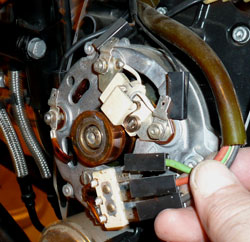 Disconnect & stator wires
4. Remove the front engine cover. Note the location of all wire
connections, make notes if necessary, and disconnect all the wires
from the alternator housing
(a total of 6 wires, except on / 5s which have 5 ).
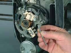 Stator cover screws removal...
 Carefully pry the stator loose
5. Remove the 3 small socket head screws from the alternator cover. Carefully lever or rock the stator windings to dislodge them from the machined seating surfaces of the crankcase, so that the housing / brush holder assembly comes off with the stator windings in one big unit. As the assembly comes off, lift the carbon brushes so they will not be damaged by the rotor end.
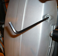
 Select 5th gear
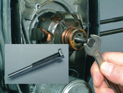 hold brake Rotor puller tool
 Rotor removed
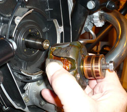
6. Remove the rotor retaining bolt with the allen wrench provided by putting the bike in 5th gear and applying the rear brake. This will prevent the engine from turning and allow loosening of the bolt. Unscrew the bolt, pull it outward and unscrew it from the rotor body.
7. Remove the rotor with the tool supplied by screwing it completely into the rotor and continue tightening after it bottoms out. The rotor is retained on a taper and can sometimes be very tight.If the rotor doesn't pop off after the bolt is getting very tight, give a short, sharp blow with a small hammer directly to the end of the puller bolt hex head and rotor body. This will usually shock the taper joint apart. If the oil seal behind the rotor is leaking, replace it now.
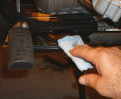
8. Install the new rotor after wiping
clean both taper surfaces, Clean the copper slip rings to remove
any trace of oil or contaminants. Re-use and fully
tighten ( to 20 ft./lb.) the original rotor bolt. Prevent crankshaft
rotation during bolt tightening in the manner described above
in step 6.
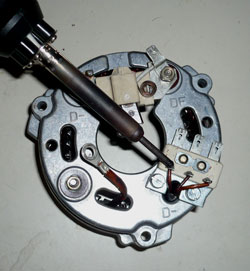
 Install the new brushes
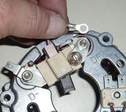 Remove the DF and D- spade terminal nuts
and spades
Remove the DF and D- spade terminal nuts
and spades
9. Install the new brushes. Remove
the DF and D- spade terminal nuts and spades. Clip the old brush
leads flush with the plate.Install new brushes by
assembling the ring terminal onto the terminal stud, and reinstall
the spades and nuts. These are original type brushes that have
had the eye ring terminal added.
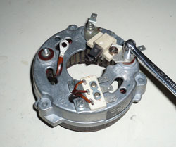
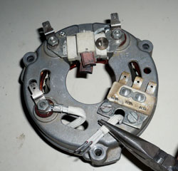
 Remove Y terminal
 De-solder stator wire
10. Remove stator from housing: Unscrew the nut and remove the Y lead from the cover stud. De ? solder the 3 wires from the connector block on the stator housing, clean all solder remnants. The old windings will then separate from the aluminum housing.When assembling the new windings to the existing cover, the 3 stator leads must be properly soldered to the connector block after desoldering and uncrimping the original stator wires.
 Fold
over excessive wire
Fold
over excessive wire
11. Install stator: Lift the brushes to prevent their being damaged by the rotor end as the stator passes over it, and seat the new stator assembly squarely into the 3 crankcase blocks.
TIP : A piece of stiff paper like
a business card can be used to form a guide for the brushes, to
prevent snagging on the rotor end.
If the stator does not easily engage the machined step on the 3 crankcase blocks, it might be desirable to use a deburring tool or Dremel-type grinder to lightly bevel the outermost edges of the blocks.
* If your stator was received from Motorrad Elektrik fully assembled, there will be a brush retainer pin fitted through the bottom of the brush holder. This holds the brushes up safely out of harm's way until the stator is fully installed. Then, pull the pin and the brushes will snap into place.
Fit the new brown ground wires to the upper 2 of the 3 stator
housing allen screws, with the longer wire to the right, when
viewed from the front. Align the 3 cover screw holes with the
threads in the case, and lightly start the screws continuing to
tighten them in a progressive manner. Make sure the cover and
windings are not crooked or binding as they draw down into the
crankcase. If the stator frame is not seated squarely in the crankcase,
damage from interference between the rotor and stator WILL occur.
Uneven or over ? tightening of the 3 screws can break the bolt
holes off and damage the cover. Tighten appropriately with a short
allen wrench, as these screws don't need to be too tight.
Diode board fasteners, early type Inner fasteners, rubber mounts
12. Remove the diode board after
noting locations of all wire connections. On 1970 through 76 models
except the R90S, and all R65 and all R80 models of all years,
the diode board is held on by a 4mm socket screw in each corner.
On R90S models and all others from 1977 onward except as noted,
the diode
board is mounted via 8mm nuts and washers on the stud ends of
a bonded rubber / metal mount. Remove the bolts or nuts and washers
on the front and remove the diode board.
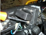
13. (next 2 steps apply ONLY to
models with rubber mounts) Remove the rubber mounts and install
the solid mounts. The 4 inner mount nuts are accessed by removing
the top engine cover, over the starter, held down with ( 2 ) 5mm
socket head screws. This is close quarters work, best done with
patience and
a small wrench or universal socket. Or,try sticking the nuts into
the end of a length of flexible tubing or hose to hold and lightly
turn the nuts till they start. On some engines, the crankcase
breather hose should be temporarily removed from its fitting for
better access to the fasteners on the right side. Install the
new solid mounts to the crankcase, but don't tighten the inner
nuts yet, so the diode board holes will be able to align with
the mount studs.
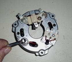
Attach blue D+ wire securely Ground wires : short to left, longer to RT
14. Install the new diode board onto the new mounts, after connecting the blue wire to the single spade terminal on the rear of the board, marked D+. Install the 2 brown ground wires from the stator, installed in Step 9, onto the bottom 2 diode board mount studs, under the nuts, NOT between the board and the mount like the original ground wires.
DO NOT RE-USE THE ORIGINAL, SMALL BROWN GROUND WIRES!
If reinstalled in the original configuration
they will short against solder points on the back of the diode
board,and render the system inoperative!! Cut and
remove the original ground wires entirely. Lightly seat the outer
nuts, then fully tighten the inner nuts followed by the outer
ones. When tightening the outer, lower 2 nuts, make sure the ground
wire terminals do not rotate and contact the diode bridge.
ALL OTHER MODELS:
On models using the 4 socket head screws for diode board attachment, it will be necessary to use the shorter allen screws provided. The new diode board is slightly thinner, and the old screws will bottom out too soon.
Red wires point downward Stack solenoid wires on upper nut
15. Connect the new wires: The original diode board B+ connecting wire (red) is very often damaged inside the insulation from heat and corrosion, and can cause serious voltage drop and charging deficeincy.The red wire connects to the diode board multi ? connector B+ terminal on the lower, right corner of the board (viewed from front ). All of these terminals are in common and it does not matter which one is used, except as noted below. The best routing is usually achieved by connecting to the vertical spade terminals. The ring terminal of this red wire connects at the threaded upper stud with 13mm nut on the starter solenoid, where the large main battery positive cable connects. The difference in size of the spadeterminals old wire vs. new is of no consequence.
If the original wire is in good condition, just add the new wire to provide the maximum benefit of reducing the load on both wires.
Special note for red wire on Slash
Fives : Connect the red wires only to the diode board terminals
that point downward.Attaching to the terminals
pointing upward can cause the red wire terminals to contact the
engine when installing the diode board and this would cause damage
to the diode board as soon as the battery was re-connected. Only
the /5 models are affected this way.
Diode board, stator, and wire routing
Connect the yellow wire from the diode board Y terminal on the
front to the single
terminal marked Y on the left, middle of the alternator cover
( viewed from the
front ).
Connect the 3 black wires from the
diode board ( encased in the woven, hi-temp sheathing) to the
3 terminal block on the front of the alternator cover. Both the
diode board and the terminal block are marked U, V, and W, but
it makes no difference whatsoever as to which terminals these
3 wires connect.
Reconnect the 2 brush holder wires to the DF and D- terminals
as original.
16. Double check all connections
and fasteners, and make sure all wiring is secured and routed
so that abraision, cutting or chafing will not occur when the
front engine cover is reinstalled and the screws are tightened.
If the cover does not fit perfectly flush on the engine, STOP
AND FIND OUT WHY !! If the cover screws are tightened with a wire
caught under the cover somewhere, IT WILL BE CUT WHEN THE COVER
SCREWS ARE TIGHTENED !!
Reconnect the battery ground cable, turn on the ignition and verify the red charge light is brightly illuminated. Start the engine and verify that the red charge light goes out with engine revs up, and note that it will return if the engine is allowed to idle for a minute or so. When the red light operates consistently in this manner, it indicates normal operation of the charging system.
NOTE : The red light may seem to
come on at idle sooner than it did before, and may take an extra
couple of hundred RPM to extinguish. This is characteristic of
the new system, and does not mean there is a problem.
17. Install the resistor for the Charge Light By-Pass Circuit
By adding this resistor to the charging light circuit, the system will continue to charge the battery even if the warning light bulb burns out. Instead of an open circuit to the rotor, the resistor will provide the path of next lower resistance for the exciter current to reach the rotor.
CONNECTIONS : The green end of the
bypass resistor wire connects to the ignition coil terminal that
has
green or green / blue wires already connected to it. Or, if it's
more convenient, connection to any other solid
green wire on the motorcycle ( such as found inside the headlight
shell ) will be OK. Connection must be to a
switched, 12v current source. This provides an alternative power
supply for the rotor exciter current since it
usually comes through the bulb.
Locate the light blue wire from
the charging light D+ / 61 circuit : this wire connects to the
voltage regulator
, the D+ terminals on the back of the diode board, and one side
of the charge warning light, all part of the D+
/ 61 circuit. Tapping into this circuit at any point will provide
the desired connection. Possible access points
are found thusly :
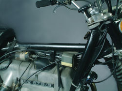
1970-76 models : use either of the
2 blue wires connected to the bottom of the starter relay, under
the fuel
tank on the left side of the frame backbone. The blue wire is
also readily accessible in the headlight shell of
1970-73 models, at the charge light bulb socket.
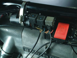
Connector location, 1977 ? 95 models.
Look for the white plastic connector, blue and black wires.
1977 ? 95 models : the blue wire is present in a white plastic,
square connector which also has a larger
diameter black wire in it. This connector is found underneath
the fuel tank, secured to the left side of
the frame lower tube, nearest the engine.
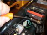
Tap connector to blue D+ wire Tap
connector to switched green wire
The line tap connectors can be used to provide a quick connection
to the blue and green wires on the
cycle harness. If available, fill the tap connector with dielectric
grease or petroleum jelly, then squeeze
it together with pliers until the halves firmly latch together.
Establish the correct length needed for the resistor
wire, crimp on the connectors firmly. Push the connectors on the
ends of the
resistor wire firmly on to the tap connectors.
Use cable ties to tie off any excess length of wire, and to prevent
movement : too much flexing of the
wire might cause it to break inside the insulation and fail the
resistor. Install the cable ties at each end of
the black heat ? shrink section in the middle of the wire for
best support. Secure to the main harness or to a
frame tube.
NOTE : This resistor circuit should
only be added to motorcycles that have a volt meter or other means
of
monitoring battery voltage. If the warning bulb blows, the system
will continue to charge but if the
charging system stops working for any reason there will probably
be no warning of a problem until the
engine quits from lack of ignition.
A voltage monitor of some sort will
give plenty of warning of a discharging battery and allow appropriate
actions to be taken BEFORE becoming stranded !!